General Information
The following information provides general equipment and service information that will help you to use this manual to properly repair and maintain the machine.
The equipment operating specifications.
| Feature | Specification |
|---|---|
|
Consoles |
LED consoles: P30, P31 Touchscreen consoles: P62 and P82 |
|
Converging Adjustable CrossRamp® |
levels 1 - 20 Stairarm wheel: Single polyurethane wheel with over-sized axle and sealed bearings. |
| Upper Arms |
EFXxx5: Moving arms |
|
Resistance |
Dual stage 3-phase hybrid generator / eddy brake current system to control the applied resistance levels. Levels: 1 - 20 |
|
Heart R m n n rate |
• Touch Handheld handlebar mounted heart rate sensors. |
|
Max User Weight |
Maximum exerciser weight: 350 lbs (159 kgs) |
|
Dimension/Weight |
Length 85 in / 216 cm
|
| Power |
Machine: Self-powe |
Model Numbers
The product model number is a six digit alphanumeric code "AAAXXX" containing the following components. Use the Product Model Number table to interpret the product number code.:
Product model number format: "AAAXXX"
- "AAA" - three alpha character product type designator
- "X" – 1 digit numeric product line designator
- "X" – one digit numeric console type designator
- "X" – one digit numeric feature level designator
Example
Product model number: TRM833
- TRMTreadmill – Treadmill
- 8 – Experience Line
- 3 – P30 console
- 3 – Fixed ramp
Product Model Number Table
| PRODUCT TYPE | PRODUCT LINE | CONSOLE | FEATURE LEVEL | |
|---|---|---|---|---|
| TRM: treadmill EFXElliptical Fitness CrossTrainer: elliptical AMTAdaptive Motion Trainer: AMT UBKUpright Bike: Upright RBKRecumbent Bike: Recumbent |
8-Experience, Premium 7-Experience, 6-Assurance, Standard 4-Precision, Consumer 2-Energy, Consumer |
8-P80, P82 6-P62 3-P30, P31 2-P20 1-P10 |
7 | EFX: Fixed Ramp/Moving Arms |
| 5 | TRM: High Speed/Decline AMT: Moving Step Height EFX: Moving Ramp/Moving Arms |
|||
| 3 | TRM: Fixed Ramp
AMT: Fixed Step Height EFX: Moving Ramp/Fixed Arms |
|||
| 1 | EFX: Fixed ramp/Moving Arms | |||
Serial Numbers
About
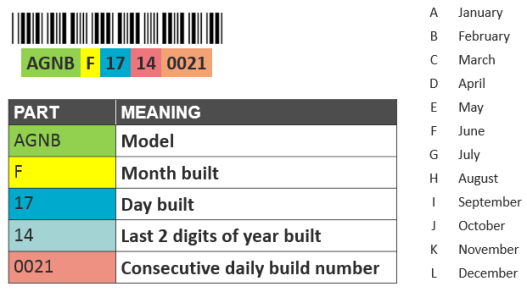
The serial number uniquely identifies each machine. The serial number is an alphanumeric code comprised of a four character model designator, a 1 letter build month code, a 2 digit day built, a 2 digit year built and a four digit consecutive daily build number.
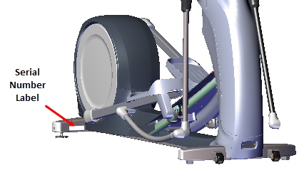
Serial Number Label Location
The serial number label is located on the hood and frame.
|
|
Note: Always use the frame serial number label to verify the machine serial number. Do not use a label attached to a plastic cover, the cover may have been replaced from a different machine. |
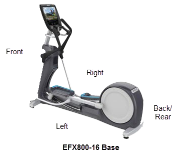
The equipment orientation (front, right, left, back) used in manual is referenced to a user standing on the equipment facing the console.
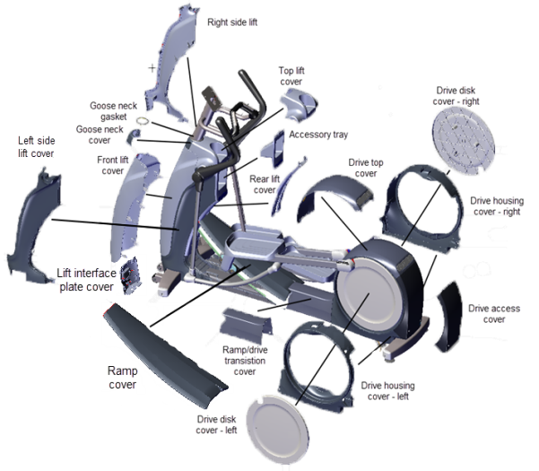
Equipment cover and access panel locations.
For cover removal and installation, see Covers and Panels Replacement.
Tools and supplies required to complete the machine service and repair.
Tools
| US and Metric Hex Key set | Standard and Phillips screw driver set |
| US SAE and Metric Wrench set | External 0.047" Retaining Ring Pliers |
| TorqueTorque is a measure of the force that can cause an object to rotate about an axis. Bolt/nut example: 5 nM torque is equivalent to 5 newtons of force applied one meter from the center of the bolt, 6 ft-lb is equivalent to 6 lb of force applied 1 foot away from the center of the bolt. wrench | DVM Multimeter |
| US SAE and Metric socket set | Belt Tension Gauge (recommended Kent-Moore BT-33-73-F) |
| US SAE and Metric Hex Key Socket Bit set |
Supplies
| Super Lube Gel with Teflon by Permatex | Cleaning rags |
| Mobil 1, NLGI 2 Teflon Synthetic Grease | Cleaner Degreaser (Simple Green) |
| Loctite 243 Blue Medium Strength Threadlocker | Cable ties (1- 3/4", 3", 4" lengths) |
Fastener Torque Specification
System component fastener torque specification:
| System Component | Specification |
|---|---|
| RFRadio Frequency: Identifies electromagnetic signals with frequency spectrum between the 3 kHz (3,000 hertz) to 300 GHz (300 billion hertz) range. coax connector | 2.4 in-lbs (0.271 Nm) |
| Display fasteners | 180 in-lbs (20 Nm |
| Set screws | 300 in-lbs (34 Nm) |
| Plastite screw fasteners | 20 in-lbs (2.3 Nm) |
| Flathead screws | 25 in-lbs (2.8 Nm) |
| Input Drive Assembly fastener | 180 in-lbs (20.3 Nm) |
| Step-up Pulley/Tensioner and Tension Assy fasteners | 180 in-lbs +/- 54 (20.3 +/_ 4.5 Nm) |
| Generator/Eddy Brake Assy fasteners | 180 in-lbs +/- 54 (20.3 +/_ 4.5 Nm) |
| Linkarm fasteners | 300 +/- 90 in-lbs (34 +/- 10 Nm) |
| Crank Retention Plate Fastener | 30 +/- 9 in-lbs (3.4 +/- 1 Nm) |
| Yoke Ramp bolts | 330 in-lbs (27.5 ft-lbs or 37.2 Nm) |
Belt Tension Specification
.Drive belt tension specification:
| System Component | Specification |
|---|---|
| First Stage Drive Belt Tension - New Belt(1) | 140-150 lbs (63.5 - 68 kgs) |
| First Stage Drive Belt Tension - Used Belt(1) | 125 - 135 lbs (56.7 - 61 Kgs) |
| Second Stage Drive Belt Tension - New Belt(1) | 110-120 lbs (50- 54.4 kgs) |
| Second Stage Drive Belt Tension - Used Belt(1) | 92 - 105 lbs (43 - 47.6 kgs) |
| (1) New belt tension applies to new belt first time installations. Used belt tension applies to reinstalling an existing belt or re-tensioning an existing used belt. | |
.
Bolt grade markings are used to categorize bolts according to the bolt material, manufacturing process, and mechanical properties.The grade of the bolt is stamped on the head of the bolt.
US SAE bolts: The bolt grade markings are determined by the number of the lines stamped on the head of the bolt. The number of lines is always two less than the grade of the bolt. Count the lines, add two, and you can determine the grade of the bolt.
Metric bolts: On metric bolts, the bolt grade is identified by a bolt grade number stamped on the head of the bolt.
|
|
CAUTION: Always replace bolts with the same grade bolt. If you don’t know the grade of the replacement bolt – DO NOT USE THE BOLT. |
Bolt Grade Markings Chart
Example bolt grades used on Precor equipment (may not represent all bolt grades). Always match the replacement bolt grade marking to the removed bott grade marking.

|
|
IMPORTANT: Always purchase OEM replacement parts and hardware from Precor. If you use parts not approved by Precor, you could void the Precor Limited Warranty. Use of parts not approved by Precor may cause injury. |
Exploded View Diagram and Parts List
There is a copy of the parts Exploded View Diagram and Parts Identification List included in the Exploded View Diagram & Parts List chapter that you can use as a quick reference. It is recommended that you go to the servicer partners ![]() Precor Connect (or Precor Connection) website to view the most current parts information including the Exploded View Diagram and Parts Identification List.
Precor Connect (or Precor Connection) website to view the most current parts information including the Exploded View Diagram and Parts Identification List.
-
 Precor Connect Partner website

.
Only use products from the following list of approved lubricants:
| Lubricant | Description |
|---|---|
| Grease |
Use only NLGI class 2 PTFE synthetic grade grease. Use of unapproved lubricants may void the product warranty. Recommended brands (or equivalent): • Mobil 1® synthetic grease • Super Lube® with Teflon |
|
|
CAUTION: Do not use petroleum based lubricants on mechanical components such as the lift, as this may result in degradation of nylon gearing mechanisms. Use only synthetic lubricants such as "Super Lube with Teflon" or "Mobile One Synthetic" grease (RED). |
Only use the following approved cleaning products to safely clean and prevent damage to the machine surfaces.
Approved Cleaning Products:
- General Equipment Surfaces:
- 1 part mild soap to 30 parts water (recommend Simple Green® cleaner or equivalent).
- Athletic equipment cleaner, 9x7 pre-saturated wipes (ATHLETIX PRODUCTS).
- Enivir O Safe oxygen enhanced cleaner or Enviro Safe glass and multitask cleaner concentrate.
- Consoles and PVSPersonal Viewing System display.: a diluted solution of one part 91% Isopropyl alcohol to one part water.
Cleaning Procedure
- Wipe down equipment using a soft lint-free cloth using only the recommended cleaning solution. Always spray cleaning solution directly onto the cleaning cloth and not directly onto the equipment surface to avoid equipment damage due to excessive moisture.
|
|
CAUTION: Do not use acidic cleaners and do not spray directly onto the equipment surfaces. |
- Rinse surfaces using a clean lint-free cloth dampened with water only.
- Then completely dry with another clean lint-free cloth.
The EFX is a self-powered unit that does not require external power to operate. Pedaling will turn an internal generator which generates the power required to supply the internal electronics, lift motor, P10/P30 consoles, and battery charging functions.
Cable TV "CATV" RF input signal power requirements
For touchscreen (P62, P80, and P82) consoles or PVS displays, there is a minimum RF input power requirement to properly supply CATVCable Television (aka Community Access Television) is a system of transmitting television programming to consumers via radio frequency (RF) signals transmitted through coaxial cables signal to the consoles.
- Analog video power: +5 dB1) DB or DBR: treadmill dynmaic break resistor 2) Decibel (dB): In electronic systems, the decibel (dB) is a logarithmic unit of measurement used to express the system power gain (+dB) or loss (-dB) in decibels (dB). dB (power) = 10Log Pout/Pin) or, in terms of voltage, dB (power) = 20Log (Vout/Vin). to +10 dB RF power with a +40 dB minimum channel to noise ratio (at each console).
- Digital RF power: -5 dB to 0 dB (at each console).
For MYE displays.
- Analog video power (at each display): - 30 dB to +20 dB RF power with a (+40 dB C/Ncarrier-to-noise ratio: The ratio of power in an RF carrier to the noise power in the channel. CNR is defined as the ratio of the received modulated carrier signal power C to the received noise power N after the receiver filters: in terms of power: CNR = C/N, in terms of decibles CNR(dB) = 10Log(C/N) = C(dBm) – N(dBm). (Channel to Noise ratio).
- Digital RF power (at each display): -5 dB to 0 dB.
Using an RF wall outlet
If a wall RF outlet is used to power several consoles in series for a row of equipment there is a minimum RF power requirement at the outlet of +35 dB at +40 dB minimum channel to noise ratio for analog video and a +25 dB for Digital video. RF signal strength of +35 dB can power 17 to 19 consoles in a single row when properly tapped out.
Ethernet (LAN) input signal requirements
Precor recommends a dedicated CAT6 Ethernet feed to each equipment location.
Communication Requirements:
- 512Kb/s up
- 5-10Mb/s down
- Switch Ports: 80, 123, 443
Touchscreen (P62, P80, and P82) console Preva PBSPreva Business Suite communication protocol
The touchscreen consoles use a security token for communication to the Precor servers. The security token is a hash string that is sent with every API call from the FE’s to the Amazon Cloud. The security token originates after the equipment is registered at the location. The console issues a ‘Call’ which returns the registration token and the fitness equipment URL. Every event after that uses the URL and the token to validate/authenticate communication with the Amazon servers and Preva Business Suite (PBS).
All communication with Precor servers is currently done via outgoing (originating from the console) HTTPS sessions. The console utilizes NTPNetwork Time Protocol (NTP) is a networking protocol for clock synchronization between computer systems over packet-switched, variable-latency data networks. to set its clock and for synchronization. At no time is Precor connecting to the customers facility network to "push" any data. The console initiates all data requests.
.
